Design of Injection Mould for Car Lamp Decorative Cover ABS+PC
1 Structural analysis of decorative cover of headlight
Outer surface of lamp trim cover is smooth, there are 5 studs and 4 undercuts on inner surface, as shown in Fig. 1(a). In order to prevent outer surface of molded plastic part from shrinking, stud base is hollowed out, the two sides of base are placed on the side of plastic part, as shown in Fig.1 (b). Root of inverted buckle 1 is in close contact with side wall of plastic part. In order to prevent shrinkage, root of inverted buckle 1 is hollowed out, as shown in Fig. 1 (c).
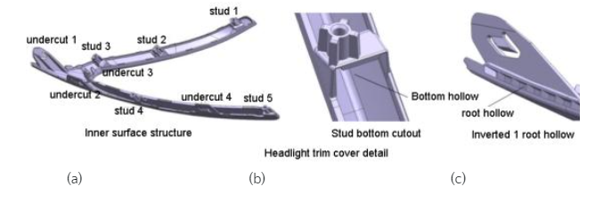
Fig. 1(a) undercut, (b) Bottom hollow , (c) Root hollow
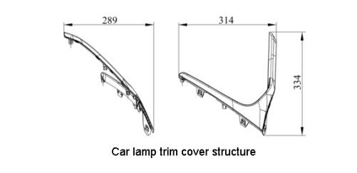
Taking center line of decorative cover stud as vertical direction, size of plastic part is shown in Fig. 2, wall thickness is 2.5 mm, and injection material is modified ABS+PC.
2 Mold structure and demolding scheme
There is a decorative cover next to two headlights of car, shape and structure of the two are symmetrical to each other. Lamp decoration cover mold adopts a 2-cavity structure, which can not only improve production efficiency, but also balance force of mold, effectively prevent deformation of mold plate, and prolong service life of mold.
Demoulding scheme: ①Set axial direction of inner surface stud as mold opening direction; ②Stud is demolded with a push tube, and hollow base of stud is demolded by an oblique push mechanism; ③Slope of parting surface at 3 position of upside down is large, so use inclined push rod to demould; ④ Use slide block to demould at positions 1, 2, and 4. If inclined push rod is used for demoulding, interference will occur.
2.1 Structure of movable and fixed molds
Taking axis direction of stud as mold opening direction, parting surface of the two plastic parts to be formed is arched after being placed relative to each other, and maximum space area enclosed is 628 mm * 314 mm * 334 mm. In order to strengthen strength of movable and fixed formwork, prevent their deformation, length and width of movable and fixed formwork are increased by about 200 mm than length and width of area enclosed by the two plastic parts. Distance from bottom of fixed mold cavity to bottom of fixed formwork is 92 mm, distance from bottom of movable mold cavity to bottom of movable mold plate is 143 mm, both movable and fixed mold cores adopt an integral structure.
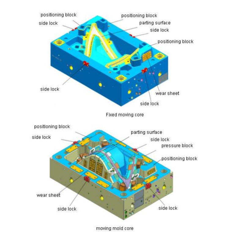
In order to meet appearance requirements of plastic parts, materials with good polishing performance and corrosion resistance are selected for fixed mold plate, such as S136; materials with excellent cutting performance, such as 2344, are selected for movable mold plate. In order to improve sealing effect of parting surface of movable and fixed molds, sealing width of parting surface is set to 30 mm, parting surface other than sealing position is evacuated to a depth of 0.5 mm, so that clamping force is all concentrated in sealing area of parting surfaces; in order to prevent injection molding machine from pressing too much mold and crushing parting surface, a pressure block is set on movable mold plate, structure of movable and fixed mold cores is shown in Fig. 3.
2.2 Positioning mechanism
Guide post and guide sleeve not only serve as guiding mechanism for movement of movable and fixed mold plate, but also bear transverse shear stress of mold. Guide post and guide sleeve of φ60 mm are selected, and size of mold base is 1 050 mm * 700 mm. In order to reduce transverse shear stress on guide post and guide sleeve, a pillow structure is designed on parting surfaces of movable and fixed molds, positioning blocks are designed on both sides of mold base, and side locks are installed on four sides. Through stop function of pillow position, positioning block and side lock, dislocation of moving and fixed molds can be prevented; in order to improve positioning accuracy, inclination of mating surface of pillow position and positioning block is set to 5°, and a wear-resistant sheet is installed on inclined surface. Material of wear-resistant sheet is 40Cr, and heat treatment hardness is 47~50 HRC. Material of side lock is SDK11 steel with a heat treatment hardness of 50~60 HRC.
2.3 Inclined push mechanism
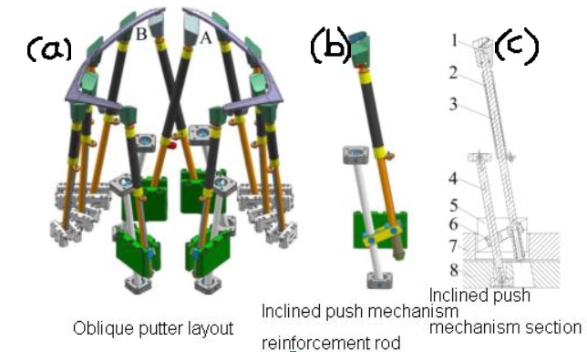
Outline of plastic part is relatively narrow, each cavity has 6 inclined push rods, and layout is relatively dense. In order to prevent interference of inclined push mechanism, inclined push block is set in area outside contour of plastic part, so that layout of inclined push mechanism is more flexible. Mold adopts a structure of 2 cavities, and 2 plastic parts to be formed are placed opposite each other. In order to prevent interference of A and B oblique push mechanisms in Fig. 4(a), oblique push rods are staggered from each other; in order to ensure strength of oblique push rods , diameter of inclined push rod is set to φ20 mm. Inclination angle of stud 1 and stud 5 is large, and torsional force on inclined push rod is large when pushing out. In order to prevent deformation, a reinforcing rod is added next to it, as shown in Fig. 4 (b), reinforcing rod bears twisting force when pushing out; in order to prevent wear of inclined push rod, install a copper tube sleeve on inclined push rod. Inversion of plastic part is inclined downward, and inclination angle is large. In order to ensure smooth demoulding of plastic part, chute of lifter seat is designed to be inclined according to inclination of inversion, as shown in Fig. 4 (c).
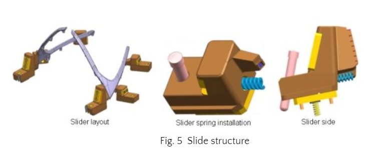
2.4 Slider structure
Due to dense layout of oblique push rods, oblique push rods 1, 2, and 4 cannot be used for inclined demoulding, otherwise interference will occur when pushing out. Demoulding structure of inclined guide column + slide block is adopted, slide block distribution is shown in Fig. 5 (a). Because size of undercut is smaller, corresponding slider core is also smaller. Due to smaller size of parting surface, corresponding slider core is also smaller. Due to irregular parting surface, centerline of slider seat cannot coincide with centerline of slider core when designing slider seat. In order to prevent block from being stuck due to uneven force on slider when mold is closed, a spring is installed at the bottom and front of slider, spring assists inclined guide column to guide slider movement, as shown in Fig. 5.
2.5 Gate system
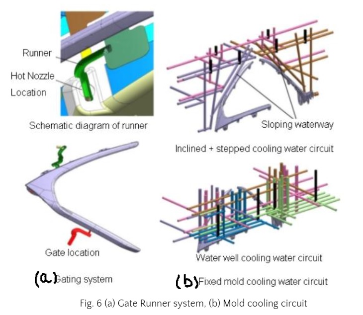
Lamp decoration: Lamp cover is a decorative part, quality of outer surface is high, there can be no traces such as gate and shrinkage. Therefore, a gating system that converts hot runners to ordinary runners is used, as shown in Fig. 6, and material is fed from inner surface of plastic parts to be formed. Specific injection process: hot nozzle is connected to common runner, common runner is introduced into mating surface of inclined push rod and core, gate is set on inner surface of plastic part to be formed, as shown in Fig. 6(a). When inclined push rod is pushed out, it will bring out condensate in runner. Due to slender contour of plastic part, two fan gates are used for gating. According to manufacturing experience of similar molds and results of Moldflow analysis, position of gate is shown in Fig. 6(b).
2.6 Cooling system
Good cooling: A good cooling system is beneficial to prevent deformation of molded plastic parts. Mold is a 2-cavity structure. In order to control mold temperature, an independent cooling water circuit is designed for each cavity. Because lamp decoration cover is in the shape of “<“, there are 2 branches, one of which has a larger inclination angle and the other has a smaller inclination angle. According to inclination angle of different branches on plastic part, same cavity needs to be designed with 2 independent cooling water circuits, so there are 4 independent cooling water circuits on movable and fixed mold plates respectively.
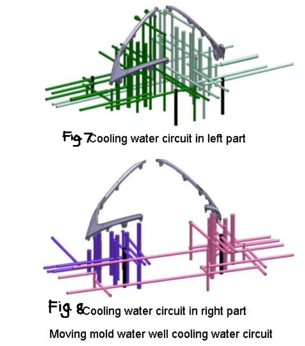
On fixed mold base, a cooling water channel combined with a straight-through water channel and a water well is used, as shown in Fig. 7. In cavity area with a large slope, a straight-through water channel is used, with a diameter of φ12 mm. In order to make distance between cooling water channel and surface of cavity same, straight-through water channel is designed to be stepped and connected by an inclined water channel, as shown in Fig. 7(a), in cavity area with a small slope, a water well cooling waterway is used, diameter of water well is φ18 mm, and bottom surface of water well is set near cavity, as shown in Fig. 7(b) .
Since there are many oblique push mechanisms on movable die, as there are many oblique push mechanisms, sliders and push rods on movable die, cooling water circuit needs to avoid these positions, it is not appropriate to design a straight-through cooling water circuit, but a well-type cooling water circuit. Movable die plate is divided into 4 cooling water circuits, as shown in Fig. 8. In order to ensure temperature of each part of mold is basically same, a water collecting block water supply structure is used, different cooling water circuits are connected in parallel to water inlet pipe of water collecting block, and a water temperature control system is installed on cooling water path. Temperature sensor automatically adjusts water flow speed according to water temperature in cooling water circuit, so as to control temperature of movable and fixed molds, so that mold temperature of each part is same.
2.7 Exhaust system
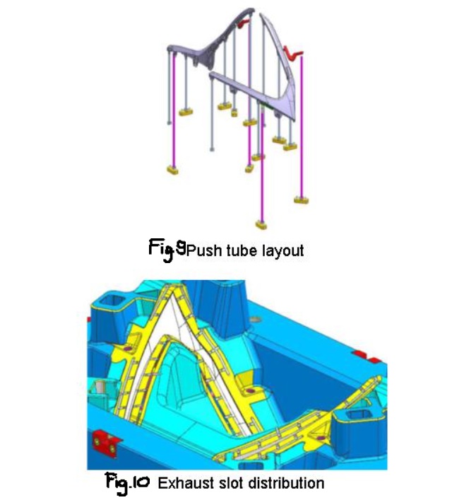
Using UG software to measure volume of plastic part is 120,011 mm3 , shape is large, outer surface of lamp trim cover should not have welding marks, scorching and other undesirable phenomena. Therefore, a good exhaust system must be designed to quickly exhaust air in cavity during injection. There are 6 inclined push mechanisms, 3 sliders, 5 push tubes and 2 pull rods on each cavity. Push tube layout is shown in Fig. 9. In order to increase exhaust effect, an exhaust groove is set on parting surface of fixed mold core along contour of plastic part (see Fig. 10). Main exhaust groove is composed of a circular arc surface, width of mouth is 6 mm, width of branch exhaust groove is 6 mm, and depth is 0.2 mm. In addition to being exhausted from exhaust groove, air in cavity can also be exhausted from gap around inclined push mechanism, slider and push tube. This exhaust system can meet needs of injection molding.
2.8 Launching agency
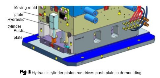
Size of mold base is 1 050 mm * 700 mm, push-out distance is 120 mm, mold structure is complex, there are many demoulding parts such as sliders, inclined push mechanisms and push tubes, distribution is uneven, its pressure center does not coincide with center of push plate. When ejector rod of injection molding machine pushes mold push plate to move, there are two hidden dangers: ① movement of push plate is unbalanced, oblique push mechanism and push rod will be worn out after long-term work, or even break; ②Force exerted on push plate by injection molding machine will be transmitted to movable die base plate and clamping screw of injection molding machine. After long-term operation, movable die base plate or clamping screw will be deformed, resulting in flashing of molded plastic parts. In order to solve above two hidden dangers, a hydraulic cylinder with a pressure of 25 MPa is installed at each end of movable mold plate, as shown in Fig. 11, piston rod of hydraulic cylinder drives push plate to move. Advantages of using hydraulic cylinders for demoulding: ① 2 hydraulic cylinders exert force on both ends of push plate at the same time, which ensures balance of push plate movement; ② force of hydraulic cylinder on push plate will not be transmitted to movable mold base plate and movable mold base plate. On clamping screw of injection molding machine, stability of mold can be ensured.
2.9 Mold structure
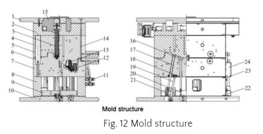
Size of plastic parts is small, each cavity is provided with 6 inclined push mechanisms, 5 push tubes and 2 pull rods. It is not necessary to design push rods to push out molded plastic parts. Top seat is fixed on push plate, which can save push tube fixing plate and save manufacturing cost. Mold structure is shown in Fig. 12.

FLUENT Co.,Ltd & Gud Mould Industry Limited